Electric Actuator Configurator Guide
Our online configuration tool enables you to configure an actuator using application attributes such as distance, load and speed; and product attributes such as size, stroke length and mountings. The instructions below will guide you through the process.
Firstly, to ensure that the changes in your configuration are up to date please navigate using the NEXT and PREVIOUS buttons at the bottom of every page. Once you’ve made any changes to your configuration select with the cursor anywhere outside the cell you have changed and wait for the 'Your configuration has been saved' message to appear in the bottom left corner of your screen.
Application
Please provide accurate details about the nature of your application.
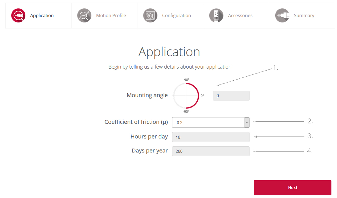
1. Mounting Angle – Will the actuator be mounted vertically upwards (90°), vertically downwards (-90°), horizontally (0°) or somewhere in between?
2. Coefficient of friction – This value represents the relationship between friction force and the normal force (μ = F / N). For more information and for typical coefficient of friction values click here.
3. Hours per day – How many hours per day will the actuator be operating?
4. Days per year – How many days per year will the actuator be operating?
Motion Profile
This is where you will describe a single cycle of your application so that we can calculate the forces required.
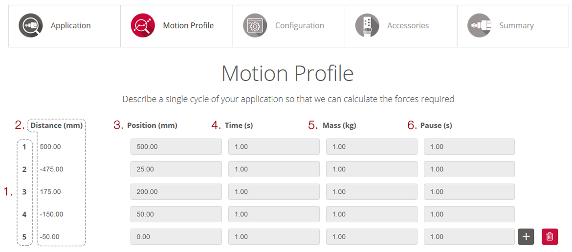
1. Steps – Each step is a single movement which consists of position, time, mass and a pause.
2. Distance – The distance the piston travels in millimetres to reach each specified position. For example, if in step 1 the cylinder moved to a position of 500mm then in step 2 you wanted the cylinder to move to a position of 25mm then the cylinder would retract by 475mm.
3. Position – This is the absolute position that the cylinder will move to, during this step.
4. Time – This is the time in seconds that the cylinder is required to move the specified distance. For example, if the cylinder moved a relative distance of 100mm in a time of 1 seconds then the speed would be 0.1m/s.
5. Mass – This is the mass in kg that the cylinder will act upon during this step. This is not the weight (N) but rather the mass (kg), if you have weight then divide the weight by gravity, 9.81, to get the mass in kilograms. For example if the weight was 1000N the mass would be 1000/9.81=101.94kg.
6. Pause – Once the step has been completed how long would you like the actuator to pause for before the next step starts.
Position – Position (mm) vs Time (s) Motion Profile of one cycle:
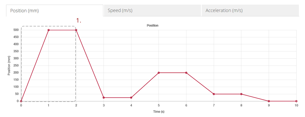
1. In the above example, in step 1 the cylinder moves 500mm in 1 seconds, then pauses for 1 second.
Speed – Speed (m/s) vs Time (s) Motion Profile of one cycle of your application:
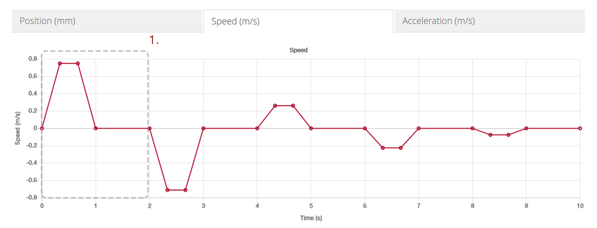
1. In the above example, in step 1 the cylinder accelerates for 0.33 seconds, maintains constant speed for a further .33 seconds, decelerates for .33 seconds, then pauses for 1 second.
Acceleration – Acceleration (m/s2) vs Time (s) Motion Profile of one cycle of your application:
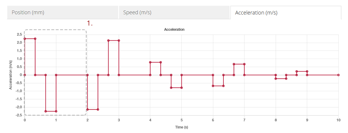
1. In the above example, in step 1 the cylinder accelerates for 0.33 seconds, maintains constant speed for a further .33 seconds, then decelerates for .33 seconds then pauses for 1 second.
Configuration
This is where you can make changes to your configuration that still meet your application requirements, such as bore size, motor and pitch.
Calculations:
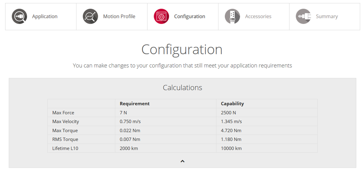
- If you select the arrow underneath ‘Calculations', a table will appear.
- Based upon the parameters specified in the application and motion profile sections, the configurator has calculated certain variables; these are given in the ‘Requirement’ column.
- An electric actuator has been configured that best fits the motion profile; the capabilities of that electric actuator are given in the ‘Capability’ column.
Configurations:
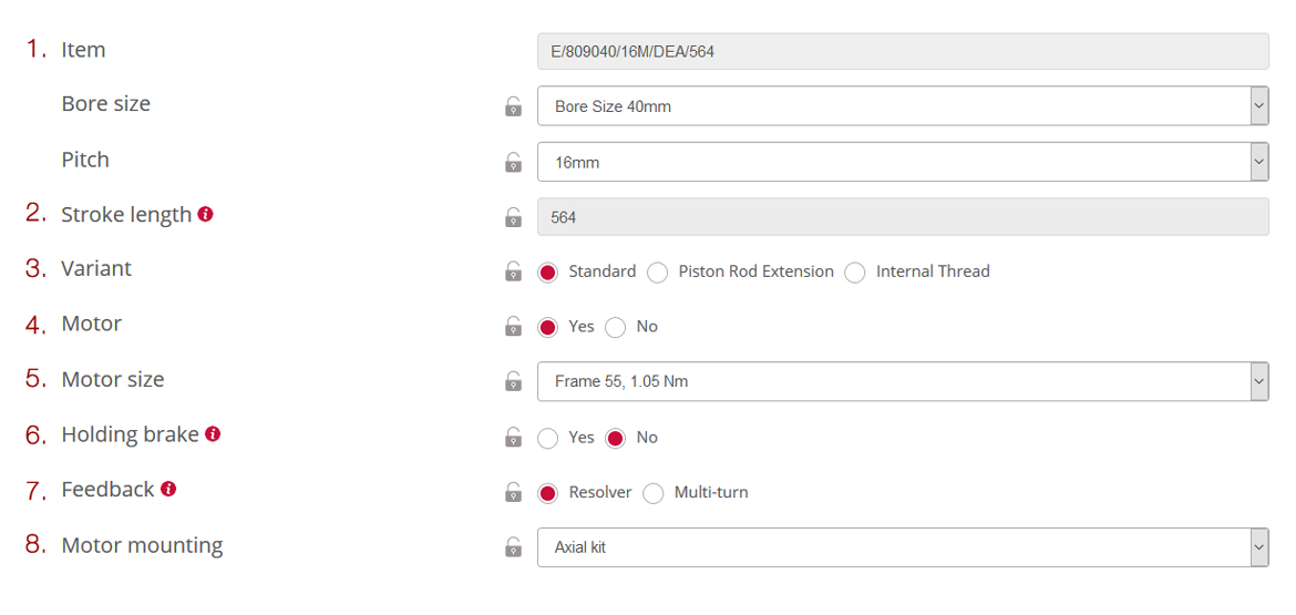
1. Item – This is the part number of the electric actuator that has been configured for your application. You have the option of changing the bore size, pitch and stroke length within a range that will still be suitable for your application.
2. Variant – You can select either the standard option, piston rod extension or internal thread.
3. Stroke length – The stroke length includes a safety factor which is 4 X the pitch.
4. Motor – The motor supplies the mechanical energy to the actuator, you can choose to have a motor or not.
5. Motor size – You can select which motor size and torque you require. To find out more about motor sizing click here.
6. Holding brake – Motors can be equipped with a mechanical holding brake.
7. Feedback – There are two feedback options - resolver or multiturn. To find out more about feedback click here.
8. Motor mounting – You can choose whether you want the motor mounted axially (behind) or parallel, with the parallel option you can mount it in either of the north, south, east or west directions.
| If you hover over the |  | symbols they will give you more information about a certain parameter. |
| Clicking on the |  | symbols commit those values so that they carry precedence over other changes which you may wish to make. When committed the lock symbol will turn red: |  | . |
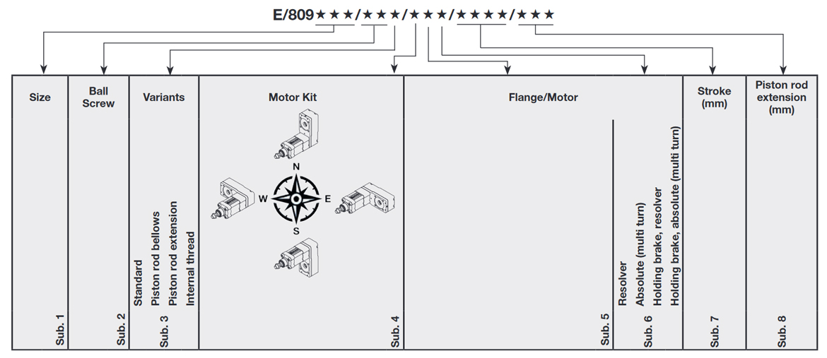
Cylinder Variants:
Accessories
This is where optional accessories and mountings can be added to complete your configuration.
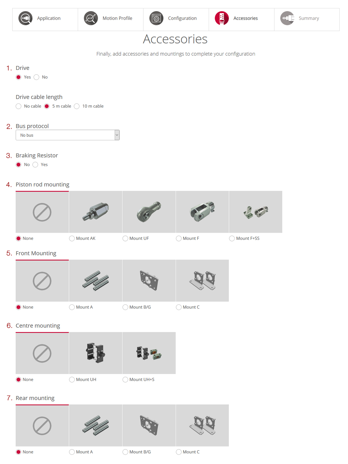
1. Drive – If you select a motor you can select whether you want a drive and the drive cable length.
2. Bus protocol – You have the option to choose which BUS protocol you would like with the drive, you can select from PROFINET, PROFIBUS, EtherNet/IP EtherCAT, CANopen, DeviceNet and No bus.
3. Braking resistor – Safely deals with any excess energy placed on the drive.
4. Piston rod mounting – Choose the type of Piston rod mounting, either Mount AK, Mount UF, Mount F, Mount F+SS.
5. Front mounting – Choose the type of Front mounting, either Mount A, Mount B/G or Mount C (mounting options will vary depending on the configuration).
6. Centre mounting – Choose the type of Centre mounting, either Mount UH or Mount UH+S.
7. Rear mounting – Choose the type of Rear mounting, either Mount A, Mount B/G or Mount C.
Note - A situation may arise where you application requires engineering validation by our internal team. In such cases, the below warning message will appear. You can proceed and submit the quote as normal, we will be in touch with you.

Summary
This is where your complete configuration will be shown.
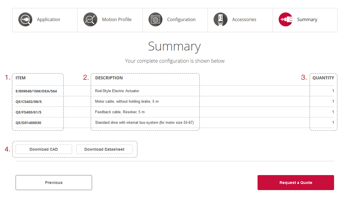
1. Item – Provides you with the part numbers for different components in your configuration.
2. Description – Provides you with brief descriptions of different components in your configuration.
3. Quantity – Provides you with the quantity of different components in your configuration.
4. Download CAD or Datasheet – You have the option to download a computer aided design (CAD) file of your configuration and a datasheet for this range of electro-mechanical actuators.
If you are happy with the summary shown, click request a quote, enter your contact details, and add any additional comments or requests if required.